Group B (Physical)
Archive: 2024
This page preserves the original 2024 guidelines content as-is for historical reference. For the current rules, see the pages under "Competition" and "Tracks".
 | Society of Petroleum Engineers Drilling Systems Automation Technical Section (DSATS) International University Competition 2023–2024 Drillbotics® Guidelines Group B Revised 11 October 2023 |  |
Version History
| Version | Date | Section | Description |
|---|---|---|---|
| 2024.01 | 11 October 2023 | All | Initial release |
Introduction
This year marks the tenth competition for the title of Drillbotics® champion and a chance for students to learn about the drilling process from industry experts and for winning team(s) to travel and present a paper at the next SPE/IADC Drilling Conference and at an event organized by DSATS. The past years involved undergraduates, masters and doctoral students from a variety of disciplines who built innovative drilling machines and downhole tools while developing a deeper understanding of automating the drilling process. Recently, this was extended to include teams who created models of the rig, the drilling process, and various downhole interactions. Teams freely shared lessons learned, which more rapidly advances the science of drilling automation. Everyone involved claims to have had a lot of fun while learning things that are not in the textbooks or published papers. Students also participated in related events at conferences, workshop meetings and networking with industry leaders in drilling automation. This year’s contest promises to be just as challenging and hopefully as much fun. For more information, see https://drillbotics.com/
This year’s Group A competition again allows teams two options. They may compete like previous years, virtually drilling a directional well. Optionally, they may choose to focus on virtually detecting and controlling a well control event (e.g., kick). Group B will drill a 2-dimensional directional well under similar guidelines to last year, but may opt to drill a 3-dimensional well.
New for 2024
Continue with two groups
A – Virtual
B – Physical
Separate guidelines for each group to reduce confusion
Group A:
Create model (or option to use publicly available models) to simulate a virtual rig, or
Use their rig model to interface with a well control model provided by Norce using their OpenLab simulator.
Group B:
- Build and operate a physical rig to drill a 2D directional well or an optional 3D well.
For A & B: Additional credit for teams that develop a D-WIS compatible API for data interoperability.
Okay for two schools to join together for their entry.
New Group A teams are highly encouraged to use the OpenLab Drilling Simulator (https://openlab.app/) and focus on designing the controls system. The D-WIS interface and connectivity will be used to send set-points to the simulator and receive surface and downhole sensor data. Webinar training on how to use the D-WIS interface and the simulator will be provided in October. Group B teams could use the simulator to validate and verify the interoperability of their API.
Previously, teams reviewing the contest rules had to jump between the main body of the guidelines to various appendices depending on which group they chose. This year we have created separate guidelines for Groups A and B. The general information items that are common to both groups are identical. Rules specific to each group are listed in an appendix. Teams must also monitor the website (https://drillbotics.com) to check any Frequently Asked Questions (FAQs) since they become part of these guidelines.
How did the competition first come about? The origins began in 2008 when several SPE members established the Drilling Systems Automation Technical Section (DSATS) to help accelerate the uptake of automation in the drilling industry. DSATS’ goal was to link the surface machines with downhole machines, tools, and measurements in drilling systems automation (DSA), thereby improving drilling safety and efficiency. Later, at an SPE Forum in Paris, the idea of a student competition began to take shape; a DSATS sub-committee was formed to develop the competition format and guidelines further. Several universities were polled to find out the ability of academic institutions to create and manage multi-disciplinary teams. The Drillbotics committee began small in 2014-2015 to see if the format could succeed. With fine tuning, we continue along those lines as we start the 2024 process.
Competition Overview:
Group A
-
Option 1: The teams will design a control system that will virtually control their full-scale drilling system model to test and demonstrate their automated system’s capability to drill a directional well. The teams should incorporate virtual downhole and surface sensors in their automation and controls scheme. The well path will be defined by three targets provided by the Drillbotics Committee immediately before the final Phase II test. Teams can drill a 2D or an optional 3D trajectory.
-
Option 2: Teams may use the D-WIS interface standard to connect to an OpenLab simulator offered by Norce to detect and control an influx (kick).
Group B
-
The challenge requires teams to develop a small-scale drilling rig and control system to autonomously drill a directional well following a given trajectory.
-
Downhole sensors are mandatory, and their data must be included in the control algorithms.
-
The well path will be defined by three targets provided by the Drillbotics Committee immediately before the final Phase II test. Teams can drill a 2D or an optional 3D trajectory.
Phase I
-
Both groups must submit a Phase I Design Report not later than 31 December.
-
A Phase I Design Video is optional, due not later than 15 January.
-
Judges will review the reports and select finalists to be announced in early February.
Phase II
- Teams will submit a pre-recorded team presentation approximately one week before the Phase II test. Judges will review the presentation and prepare a list of questions that will be asked of each team prior to the physical test.
Tests
- Group A and B Phase II tests will be held on separate dates, to be advised in April. If possible, we will hold face-to-face tests in Germany and the USA, with an option for a virtual meeting on the same dates.
The DSATS technical section believes that this challenge benefits students in several ways. Petroleum, mechanical, electrical, and control engineers gain hands-on experience in each person’s area of expertise that forms a solid foundation for post-graduate careers. Those involved with system modeling gain insight into how models can gain sufficient fidelity to be applied to industry specific problems. They also learn where poor models or poor data can lead to incorrect outcomes. Students also develop experience working in multi-disciplinary teams, which is essential in today’s technology-driven industries. Winning teams must possess a variety of skills. The mechanical and electrical engineers need to build a stable, reliable, and functional drilling rig. Control engineers need to architect a system for real-time control, including a selection of sensors, data handling, and fast-acting control algorithms. The petroleum engineers need an understanding of drilling dysfunctions and mitigation techniques. Modeling engineers must understand all of these basics and how to organize numerous modules into a complex model. Everyone must work collectively to establish functional system requirements, often fully understood by each team member to accurately portray the drilling issues and create an integrated package working seamlessly together.
The oil and gas industry today seeks lower costs and reduced risk through efficiency and innovation. Many student competitors may discover innovative tools and control processes that will assist drillers in speeding the time to drill and complete a well. This includes more than a faster ROP, such as problem avoidance for dysfunctions like excessive vibrations, stuck pipe, and wellbore stability issues. Student teams built new downhole tools using 3D printing techniques of designs that would be difficult, if not impossible to machine. They used creative hoisting and lowering systems. Teams modeled drilling performance in particular formations and adjusted the drilling parameters accordingly for changing downhole conditions. While they have a lot to learn about our business, we have a lot to learn about their fresh approach to today’s problems. Good Luck!
The Drillbotics® Committee
Contents
- Introduction
- Objectives for the 2022 Competition
- Background
- General Competition Guidelines
- Team Members
- Safety
- Expenditures
- Other Considerations
- Project Timeline
- Project Reports
- Group A and Group B Prizes
- Terms and Conditions
- Marketing
- Appendix A: Group B Project Definition
- Appendix B: Automation & Interface Design
- Appendix C: Additional References
Objectives for the 2022 Competition
-
During the school year, beginning in the fall of 2023, a team of students will organize themselves to solve a drilling-related problem outlined in Appendix A below. The team should preferably be a multi-disciplinary team that will bring unique skills to the group to allow them to design and construct hardware, software and models to demonstrate that they understand the underlying physics, the drilling issues and the usual means to mitigate the issues. We cannot stress enough the need to involve students with different technical training and backgrounds. They will need to develop skills to understand drilling dysfunctions and mitigation strategies, but they must also have the mechanical engineering and controls capabilities to model, design the rig/drilling package and develop the controls system. Even when the project involves only software, an understanding of the physical limits of a rig’s machinery and tubulars is critical. In past years, some entrants have not adequately considered the control network and algorithms needed for autonomous drilling. They have often misunderstood the need for calibrated sensors and fast, accurate data handling. Some teams did not consider measurement errors. Teams from both Group A and B ignored uncertainty principles. All of this and more is needed to build and operate a complete automated drilling system. We encourage all teams to start out with a simple concept done well, and then build on it from year to year adding complexity when warranted. Planning for this evolution will make it easier on future team members.
-
The students should produce novel ideas leading to new drilling models, improved drilling machines and sensors, and the ability to integrate the data, models and machines that will hopefully create new, more efficient ways to drill wells in the future. Any such innovation will belong to the students and their university in accordance with the university’s written policies. DSATS and SPE waive any claims to students’ intellectual property.
-
The students, working as a multi-disciplinary team, will gain hands-on experience that will be directly applicable to a career in the upstream drilling industry.
Background
- What is DSATS?
DSATS is a technical section of the Society of Petroleum Engineers (SPE) organized to promote the adoption of automation techniques using surface and downhole machines and instrumentation to improve the safety and efficiency of the drilling process. More information is available about DSATS at the DSATS homepage.
- Why an international competition?
DSATS and the other technical sections, as part of the SPE, are a group of volunteers from many nations, connected by their belief that drilling automation will have a long-term, positive influence on the drilling industry. This diversity helped to shape the direction of the organization. The group feels that the industry needs to attract young professionals from all cultures and disciplines to advance drilling practices in all areas of the world. The winners of the competition will receive a grant for economy class transportation and accommodations to attend the next SPE/IADC Drilling Conference and will present an SPE paper that will be added to the SPE archives of One Petro1. Note that this year, the Drillbotics Committee will submit both Group A and Group B winning abstracts to the conference program committee. They will choose which of the two abstracts best fit their program. The Drillbotics committee will help the winning team from the other Group receive recognition of their achievement and have the opportunity via a different conference2 to publish an SPE paper that will be added to the SPE archives of One Petro. DSATS believes recognition at one of the industry’s leading technical conferences will demonstrate to industry leaders the extent of research and understanding the student teams have gained during the contest. Also, the practical experience with drilling automation systems increases the students’ visibility to the companies that are leading automation activities.
- Why include a safety case
Safety of personnel, equipment and the environment are always critical for any drilling operation. The industry begins any project or operation with safety in mind, and a safety case is a proven method of identifying and mitigating risks. This is no different on a small scale or for a virual operation. Safety goes far beyond personal protective equipment. Where can someone be hurt – in a lab with heavy rock samples and rotating machinery? Electrocution? High pressure leaks? Traveling to and from locations? Judges want to see how teams plan ahead in their first few meetings to identify threats and develop processes or devices to reduce the risk and severity of any incidents.
- Why include Human Factors?
Any complex engineered system that is wholly reliant upon human operators to achieve its goal is likely to experience issues. Humans are inconsistent when performing monitoring tasks, they tend to not make wholly rational decisions, are impacted by external factors and are prone to error. As technology advances and complexity increases (such as the control regimes proposed in remote drilling operations for example) such issues become more prevalent. However, many of the issues associated with such complexity can be countered by reallocating certain tasks to automation. Maintaining appropriate levels of automation and ensuring that your ‘projected’ drilling operator remains ‘in the loop’ through good interface design will be one of the key challenges you will face in the Drillbotics competition. It is imperative that teams show how they implemented human factors in their processes and interfaces, both in the creation of their rig or model and how the operators/judges will use their designs.
Students working with automated systems should learn about the risks and proper strategies to allow humans and machines to work together safely and efficiently. Reference documents are listed in Appendix B. Requirements for human factors provisions are shown in Appendix A.
- Items posted on the website are part of these Guidelines
The Drillbotics website at (https://drillbotics.com) includes official updates to the competition guidelines and schedule, as well as FAQs, photos, and previous entrants’ submittals and reports and numerous reference documents. Any updates to the guidelines posted on the Drillbotics website via FAQs or blog entries from the Committee are considered to be an official revision to these Guidelines.
- Questions should be directed to the competition email at competition@drillbotics.com. Teams must provide the reference number of the section of the guideless when you ask questions. Questions and answers will be incorporated into the FAQs periodically.
General Competition Guidelines
-
Entrants to Group A challenge have the option to sign up to do a well control challenge. They will need to use OpenLab Drilling simulator (https://openlab.app/) with the D-WIS interface.
-
Teams also have the option to work on a 2D or optional 3D steering challenge. They will develop a drilling system model that represents a full-scale system and corresponding control scheme to virtually drill a directional well to a given trajectory as efficiently as possible within constraints of safety and economics.
-
The Group A challenge does not involve building a rig or drilling system. The teams will design automation and control modules to develop a virtual drilling system (i.e., computer models) to test and demonstrate the controls. Teams that develop modules that can updated in future years find that their code is stronger than a complete re-write.
-
The Group B challenge requires the design, construction, and operation of a physical mini-rig to physically drill a directional well to a given trajectory as efficiently as possible within constraints of safety and economics. Teams may work on a 2D or optional 3D steering challenge. The guidelines for Group B are published separately.
-
The contest covers only the drilling of one hole section. There is no need to run casing. There is no need for automated pipe handling at the surface. There is no logging or cementing. This is just a drilling problem. However, teams should consider sampling and surveying and dealing with uncertainty.
-
Judges want to see evidence that teams know about drilling and modeling aspects of well construction. Because teams will either build or model a physical rig and downhole conditions, they must specify the assumptions made about their project. Allowing judges to understand “why” you made certain choices affecting the evaluation of your project.
-
While the teams will have to meet minimum competition requirements, any exceptional contributions “above and beyond” the main theme will be rewarded with additional points to encourage creativity and innovation.
-
Teams are free to choose the hardware and software most suited to their design except where explicitly specified. Teams are free to choose any software language. Judges would like to see an explanation of the reason certain hardware or software was selected.
-
Teams are encouraged to review the design reports, presentations, and test recordings available on the website, since these include designs that worked or didn’t work and students thoughts about their earlier choices.
Team Members
-
DSATS envisions that the students would be at least at the senior undergraduate or Masters level, well versed in the disciplines needed for such a project. The core team shall consist of at least three (3) team members and no more than five (5). Contributions from other team members is allowed, and all contributors should be recognized in the Phase I Design Report. The travel grant for the winning team will be limited to five (5) team members and one (1) supervisor due to budget constraints.
-
Any team that loses team members during the project can recruit a replacement. Note any changes to the team membership or the faculty advisor in the monthly reports. Include the email address of the new member(s). At least one member of the core team must be a Petroleum Engineering candidate with sufficient coursework completed to understand the physics relating to the drilling problems and the normal industry practices used to mitigate the problem. For universities that do not have a petroleum engineering program, two schools may join efforts to compete as a single entity (see 5.6)
-
Students with a background in mining, applied mathematics, mechanical and electrical engineering, as well as controls, mechatronics and automation or software development, are the most likely candidates, but students with any applicable background is encouraged.
-
A multi-disciplinary team simulates the working environment in the drilling industry today, as most products and services are produced with the cooperation of technical personnel from differing backgrounds and cultures.
-
A university may enter more than one team in a group and may enter teams in one or both groups.
-
A collaboration between not more than two universities is allowed, especially where one school may not offer a curriculum in a specific technical area needed to successfully conduct the project. The resulting team may only submit one Phase I design report. Also, the travel grant will still be limited to five (5) students and one (1) supervisor. Note: Any differences with intellectual property ownership between the two schools must be settled by the teams and shall not involve DSATS.
-
Students shall register their team not later than 15 October using the registration form on the Drillbotics website https://drillbotics.com/guidelines/. Please indicate the challenge (Well Control or 2D or 3D Steering) that the team will be participating in.
Safety
-
The team’s safety plan should consider all foreseeable hazards and methods to mitigate them. Personal protective equipment is part of a safety plan but is far from sufficient. Teams must consider risks due to handling the rock, rotating machinery, electrical shock and others. What health considerations are in place? How the team communicates with each other before and during operations is also important. Judges will grade each team on its comprehensive safety plan. This applies to both Group A and Group B.
-
Because most of the Group B rigs have equipment spinning at high RPMs, some form of protective cover must be included in the team’s rig design. A broken coupling, a loose screw or similar item becomes a projectile that can lead to serious injury to the team members, judges or visitors. Judges may decide to deny a team from competing if their design is unsafe. Similarly, Group A teams may be excluded if they have not met proper health and safety considerations.
-
The following links are a good starting point, but is by no means a comprehensive list of links:
-
OSHA Pocket Guide, Worker Safety Series: https://www.osha.gov/Publications/OSHA3252/3252.html
-
OSHA Checklist for General Industry: http://www.scosha.llronline.com/pdfs/genind.pdf
-
Expenditures
-
Teams selected to advance to the second phase must limit the cost of the physical or virtual rig and materials to US$ 10,000 per year or its equivalent in other currencies. Students may use previous work and make changes within the US$10,000 annual limit. The cost of transporting the rig to any local test sites is excluded. Student and supervisor travel is excluded. The students shall find a source of funding and report the source in the Phase I proposal. All funding and procurement should comply with university policy. These funds are intended to cover the majority of expenses for hardware, software and labor to construct and operate the team’s equipment. Teams will not be reimbursed for travel to any local competitions. DSATS shall not be liable for any expenditure other than DSATS provided material and specified travel expenses.
-
DSATS will assist, when possible, to obtain free PLCs or similar control devices and software tools from suppliers affiliated with the DSATS organization. Such “in-kind” donations shall not be included in the team’s project costs.
-
Students and universities may use other “in-kind” contributions which will not be included in the team’s project costs. Such contributions may include modeling software, laboratory equipment and supplies, and similar paraphernalia usually associated with university laboratory projects.
-
Any team spending more than US$ 10,000, or its equivalent in other currencies, may be penalized for running over budget.
-
DSATS reserves the right to audit the team’s and university’s expenditures on this project.
-
Any devices built for the project will become the property of the university and can be used in future research and competitions. Any maintenance or operating costs incurred after the competition will not be paid by DSATS.
Other Considerations
-
University coursework and credit: Each university will decide whether or not this project qualifies as a credit(s) towards any degree program.
-
The design concepts shall be developed by the student team under the supervision of the faculty. Faculty and lab assistants should review the designs to ensure student safety.
-
Construction of any equipment shall be supervised by the student team but may use skilled labor such as welders and lab technicians. The use of outside assistance shall be discussed in the reports and the final paper. DSATS encourages the students to gain hands-on experience with the construction of the rig since this experience will be helpful to the career of individuals in the drilling industry.
-
Teams building a virtual rig may create new models or improve models from other teams at the same university or elsewhere. Be aware of open source models from groups such as the Open Source Drilling Community (https://opensourcedrilling.org/). Teams must cite the original work done by others. Teams are also encouraged to share their models with the OSDC.
Project Timeline
Phase I - Design: Fall 2023
Submit monthly reports On or before the final day of each month starting in October
Submit final design to DSATS 31 Dec 2023, midnight UTC
Submit an abstract to DSATS* 31 Dec 2023, midnight UTC
Finalists to advance to Phase II Announced in mid-February 2024
*DSATS will submit an abstract to the SPE that will include excerpts from the student abstracts by the conference paper-submittal deadline, typically in mid-summer, for consideration of a paper by the conference program committee.
Phase II
Group A: Model enhancement/testing and controls development Spring 2024
Group B: Model & controls development/Construction Spring 2024
Group A and B Phase II Test May/June 2024
Project Reports
Report File Names
To avoid extra work by the committee to rename all files, teams must use this convention for all reports:
Monthly Reports
Year-Month# University Name (abbreviated). Note: this is the competition year (spring term).
Example: for the October 2023 entry from the University of Drillbotics Competition (UDC)
Use: 2024-10 UDC
Design reports
Year University Name (abbreviated) Note: this is the competition spring term.
Example: for the 2023- 2024 entry from the University of Drillbotics Competition (UDC)
Use: 2024 UDC Phase I Design Report
Monthly Report Contents
Starting in October for the fall term, the student team shall submit to DSATS a short monthly project report that is no more than one page in length (additional pages will be ignored) due on or before the last day of each month. Send all reports via email to competition@drillbotics.com. The monthly report should include:
Phase I Monthly Report Contents
-
Key project activities over the past month.
-
Literature survey, rig modeling considerations, trade-offs, critical decision points etc.
-
New or replacement team members or faculty supervisors (include their email address)
-
Cost updates
-
Significant new learning, if any
Phase II Monthly Report Contents
-
Key project activities over the past month.
-
Model enhancements, controls development updates.
-
Preliminary results of exercising the drilling model and controls
-
Cost updates
-
Significant new learning, if any
Other items of interest
To teach students that their work involves economic trade-offs, the monthly report should include the economic basis of decisions for hardware or software. It should also include at a minimum a summary estimate of team member labor hours for each step in the project: modeling, controls, testing etc. and a cost summary for hardware and software related expenditures. Also include labor for non-students that affect the cost of the project. Labor rates are not considered, as to eliminate international currency effects. Labor is not considered in the cost limits of section 7.1 but should be discussed in the reports.
Phase I Design Report
Detailed requirements for each group are listed in their respective Appendix A.
Final report, presentation and paper
-
The finalists shall prepare a project report that addresses items specific to each Group. We suggest you use the format of most SPE papers. For reference, please see http://spe.org/authors/resources/. This report may be submitted up to four weeks after the final test.
-
Finalists shall prepare a pre-recorded presentation two weeks prior to the Phase II test. Judges will review the recording and prepare a list of questions for the Q&A session that precedes the final test. Numerous examples are available online at https://drillbotics.com/archives/ and our YouTube channel https://www.youtube.com/channel/UCRTpKWHRiphNo6KeSqTcNyg
-
The reports, presentations, paper and all communications with DSATS shall be in the English language. The presentation must be made by at least one member of the student team, not the team supervisor.
Group A and Group B Prizes
Prizes and recognition — updates in progress
For the current competition cycle, prizes are being actively reworked and improved. In addition to the SPE/IADC paper publication opportunity described here, we plan to include additional forms of recognition, contingent on available budget. More updates to come.
-
The program committee of the Drilling Conference awarded the Drillbotics subcommittee a permanent slot3 in one of the drilling sessions at the conference. As per SPE’s customary procedures, the paper will be archived in OnePetro. In addition, SPE has agreed to furnish a booth4 in the exhibition area during the conference where the team can erect their rig and describe its operation to the conference attendees. Alternately, Group A teams will have an opportunity to showcase their simulation model at the booth.
-
This is an excellent opportunity for students to network with the industry.
-
The winning team, as determined by the conference program committee, will be asked to submit a paper to present at the next SPE/IADC Drilling Conference.
-
The Drilling Conference program committee will choose either a Group A or Group B winner to present at the conference. Only at their discretion will the second group receive an invitation to present. The Drillbotics Committee may fund both teams travel if it holds sufficient funds, which will be determined a month before the Phase II test.
-
The winning team will receive a travel grant5 to attend the Drilling Conference. Note that this is for a limited number of team members, not to exceed five (5) plus one (1) supervisor. Pre-approval of expenses is required.
-
Upon submittal to DSATS of a valid expense statement of covered expenses (typically a spreadsheet supported by written receipts) individuals will be reimbursed by the treasurer of DSATS for the following:
-
Round trip economy airfare for the team and one university sponsor/supervisor to the gateway city of the next SPE/IADC Drilling Conference. Entrants should use the SPE approved carrier where possible to minimize cost. Airfares that exceed the SPE rate must be pre-approved by the committee, or the reimbursement will be limited to the SPE rate. Information of reduced fare flights is available on the conference website. Please note that reservations must be made before the SPE published deadline. The departure point will be a city near the university, the student’s home, or current place of work, subject to review by the Committee. Alternately, a mileage reimbursement will be made in lieu of airfare should the entrants decide to drive rather than fly to the conference. The reimbursement is based on current allowable mileage rates authorized by the US Internal Revenue Service.
-
One rental car/van at the gateway city for those teams that fly to the conference.
-
Lodging related to one hotel room or housing unit6 per team member will be reimbursed at a rate not to exceed the SPE rate. Note that the room reservations are limited, so entrants must book their rooms early. Room and taxes for the night before the DSATS symposium, the night of the symposium and for the nights of the conference are covered. Charges for the room on the last day of the conference need to be pre-approved by the Committee as most conference attendees depart on the last day of the conference unless there are unusual circumstances.
-
A per diem will be pre-approved by the Committee each year, which will vary with the cost of living in the gateway city. The per diem is intended to cover average meals (breakfast, lunch and dinner) and incidentals.
-
Conference registration will be reimbursed. Students should register for the conference at the student rate. Early registration is appreciated.
-
-
Individual award certificates will be presented to all participants upon request, with special certificates given to all finalists. Team members wanting a certificate should send an email to competition@drillbotics.com with the spelling of their name as they wish it to appear on the certificate.
-
DSATS may provide additional awards, at its sole discretion.
-
The evaluation and all decisions on any matter in the competition by the Drillbotics judges and DSATS board are final.
Terms and Conditions
-
In no event will SPE, including its directors, officers, employees and agents, as well as DSATS members and officers, and sponsors of the competition, be liable for any damages whatsoever, including without limitation, direct, indirect, special, incidental, consequential, lost profits, or punitive, whether based on contract, tort or any other legal theory, even if SPE or DSATS has been advised of the possibility of such damages.
-
By entering this competition,
-
Participants and Universities agree to indemnify and hold harmless SPE, its directors, officers, employees and agents, as well as DSATS members and officers, and sponsors of the competition, from all liability, injuries, loss damages, costs or expenses (including attorneys’ fees) which are sustained, incurred or required arising out of participation by any parties involved in the competition.
-
Participants and Universities agree and acknowledge that participation in the competition is an agreement to all of the rules, regulations, terms and conditions in this document, including revisions and FAQs posted to the DSATS and Drillbotics websites (see section 3.1).
-
Winning teams and finalists must agree to the publication of their names, photographs and final paper on the DSATS web site.
-
-
All entries will be distributed to the Drillbotics Committee for the purpose of judging the competition. Personal information, such as email addresses will not be published, but could be divulged to other teams being copied on competition emails. Design features will not be published until all teams have been judged and a winner is announced. Previous years’ submittals, reports, photos and similar documentation will be publicly available to foster an open exchange of information that will hopefully lead to faster learning for all participants, both new and experienced.
-
DSATS and the SPE cannot provide funding to sanctioned individuals and organizations per current US law or the laws of nations that may host local contests.
-
Participants must comply with all local laws applicable to this contest.
Marketing
-
Upon request, DSATS will provide a link on its website to all participating universities.
-
If university policy allows, various industry journals may send a reporter to witness the tests and interview students to publicize the project.
-
Drillbotics is now a registered trademark. According to international law, the proper reference is to use Drillbotics® instead of Drillbotics™. The trademark reference is only needed the first time Drillbotics is referenced.
-
Any team that wishes to use the trademark on signs, tee shirts, technical papers or for other purposes may receive a no-cost license upon request. Send the request by email to the committee at competition@drillbotics.com. Upon completion of the license agreement, access to the files with the logo will be made available. Unfortunately, trademark law requires us to enforce this for everyone to maintain our trademark, so please ask for license before you use our mark.
Appendix A: Group B Project Definition
Overview
The following attached pages describe the directional objectives as well as the data/deliverables requirements. Scoring for the directional competition objective will be primarily based on how accurately the directional targets are intersected by the calculated well trajectory.
Directional Objective Requirements
Objectives
-
Hit one or more targets at one or more vertical depth(s) and X/Y coordinates
-
For the Group B competition, the starting directional plan to hit the targets will not require wellbore inclinations in excess of 30° from vertical, 15° change in azimuth, or 10” displacement (departure from the vertical axis at well center) The max displacement/inclination/azimuth are total/accumulated from the start to the end of the well path.
-
Please note: Teams should be prepared to drill any given trajectory within the specified parameters, so the coordinates will not be provided in advance of the test.
Automation Requirements
-
Drilling mode/survey mode switching must be automated (i.e. built-in survey interval and drill string movement for on/off-bottom, slide/rotation mode switching)
-
Steering requirements (e.g. toolface direction, slide length) must be calculated autonomously
-
NOTE: Steering mechanism can still require human intervention for placement and/or retrieval (e.g. whipstock) but orientation of steering mechanism must be calculated by the system and shown on the rig floor display.
-
Directional surveying process must be entirely autonomous
-
Survey qualification must be done autonomously, however secondary qualification/verification/override can be made by a human
-
Dogleg severity required to hit target(s), distance/direction to plan must be autonomously calculated at each survey station and shown on the rig floor display
Deliverables Requirements (Magnetic surveying)
-
All teams are required to provide a definitive directional survey (TXT, LAS, or CSV format) meeting the following minimum requirements:
-
Header info to include:
-
Team/school name
-
Directional Survey Date
-
Well Center Coordinates (WGS84 Latitude & Longitude)
-
True Vertical Depth Reference (in depth units above block level)
-
Grid Convergence
-
Geomagnetic model used (if applicable)
-
Magnetic declination applied (Geomagnetic model or in-field referenced)
-
Total Azimuth Correction
-
Magnetic field dip reference (Geomagnetic model or in-field referenced)
-
Total magnetic field strength reference (Geomagnetic model or in-field referenced)
-
Error model associated with well trajectory (ISCWSA/OWSG error model or otherwise)
-
If non-standard error model is being used (i.e. formulas being modified and/or coefficients being changed), error model description (using standard variable/coefficient naming conventions) and justification must be included in project design
-
Minimum Curvature calculated trajectory (using appropriate survey station interval to accurately represent the drilled wellbore position)
-
Each survey station is to include the following data:
1) Measured Depth
2) Inclination
3) Azimuth (referenced to “block north”)
4) True Vertical Depth
5) Northing (from well center)
6) Easting (from well center)
7) Dogleg Severity
-
Final survey station is to be an extrapolation to total depth at the bit.
-
All teams are required to provide plan vs. actual plots containing the following minimum requirements:
-
As-drilled trajectory and original planned trajectory shown on same TVD vs. Vertical Section plot.
-
Vertical section direction to be determined by well center-to-target bearing.
-
As-drilled trajectory and original planned trajectory shown on same X/Y plot.
-
Grid north reference to “block north”
-
[0,0] at well center
-
All teams are required to provide directional survey raw data logs containing the following minimum requirements:
-
Each log entry is to include the following data:
-
Time stamp (containing year, month, date, hour, minute, second)
-
Sensor measured depth.
-
Downhole sensor value(s) recorded.
-
Sensor axes values
-
Calculated survey qualifier values
-
-
Accepted survey indicator (if log entry is an intended survey station)
-
If secondary (i.e. human) qualification is also used, both acceptance indicators must be shown
-
Safety
1) The team’s safety plan should consider all foreseeable hazards and methods to mitigate them. Personal protective equipment is part of a safety plan but is far from sufficient. Teams must consider risks due to handling the rock, rotating machinery, electrical shock and others. How the team communicates with each other before and during rig operations is also important. Judges will grade each team on its comprehensive safety case.
2) Because most of the rigs have equipment spinning at high RPMs, some form of protective cover must be included in the team’s rig design. A broken coupling, a loose screw or similar item becomes a projectile that can lead to serious injury to the team members, judges or visitors. Judges may decide to deny a team from competing if their design is unsafe.
3) The following links are a good starting point, but is by no means a comprehensive list of links:
OSHA Pocket Guide, Worker Safety Series: https://www.osha.gov/Publications/OSHA3252/3252.html
OSHA Checklist for General Industry: http://www.scosha.llronline.com/pdfs/genind.pdf
Phase I – Design Competition
1) Prepare a safety plan at the beginning of the project and update it continually as needed.
2) Consider how you will use Human Factors within you project to improve your team processes and interactions with your model. You should include such items as:
1. Who are the operators of your drilling rig and how do their
    characteristics impact the design?

2. Which functions of your drilling rig will be automated, and
    which will be manual (refer to Ref. 2)?

3. How are you going to ensure that the operator remains 'in the
    loop' at all times?

4. The workflow that your drilling rig will follow (very important
    as this will guide your interface design).

5. The control and feedback needs for your defined operators.

6. The 'concept' of your interface design. This can be as simple as
    a 'wireframe' drawing with pen and paper, but it should show an
    appreciation of Human Factors Relevant Good Practice (refer to
    the resources provided below).
3) The first phase of the project starts in the fall, requiring teams to organize to design an automatic drilling machine to solve the project problem. It is not necessary to build any equipment in this phase, but it is okay to do so. Design considerations should include current industry practices and the team should evaluate the advantages and shortcomings of today’s devices. The design effort may be assisted by university faculty, but the students are encouraged to introduce novel designs for consideration. The design should also include a downhole sensor and a control system to automatically control the drilling process. The level of student, faculty and technical staff involvement shall be reported when submitting the design. For returning teams, the Phase I Design Report should include an analysis of data and learnings from previous (“offset”) wells drilled.
4) During the second phase, in the spring, the finalist selected by DSATS to proceed to the construction and drilling operation will use the previous semester’s design to build an automated drilling machine. As per industry practices, it is common during construction and initial operations to run into problems that require a re-design.
-
The team may change the design as needed in order to solve any problems they encounter.
-
Changes should be reported to the Committee via students’ monthly reports. A summary of all significant changes, including the reason modifications were necessary, must be included in the students’ final report.
-
Teams may use all or part of a previous year’s rig.
Phase I Design Report
The design submittal by the students shall include:
1) Student Biographies
-
Name
-
Previous degree attained – major.
-
Current degree and expected graduation date (month/year)
-
Main area of contribution to the project
-
Other information as deemed appropriate by the team.
2) A description of your safety plan that is appropriate for the project.
3) Engineering sketches or drawings of the rig concept, mechanical and electrical and auxiliary systems, if any, that explain your design assumptions
4) Include any design notes and calculations regarding rig, drillstring and other limitations for the particular modules used in your models.
5) A block diagram/flowchart of the modeled control system architecture. Describe the key features. The response time of measurements, data aggregation and control algorithms should be estimated. Explain how individual measurements are used are in the control code. Are they all given equal weight, and if not, what criteria is used to assign importance?
6) Since this is a directional drilling problem, be sure to include how downhole data is used for steering and other drilling aspects? Judges are looking for a description of the principles being applied to directionally steer the wellbore and hit the required targets with the intent to score the maximum number of points.
7) Proposed user interface/data display that shows the drilling progress in real time.
8) Cost estimate and funding plan
9) Key features for any models/modules and control software. What drilling dysfunctions are addressed?
10) Proposed data handling, i.e., inherent time delays and uncertainty.
11) The Phase I design report should include a discussion regarding the major design concept as modeled (mechanical and otherwise) with respect to the feasibility for use on today’s working rigs? If not, what would be needed to allow implementation?
Additional optional items:
12) A design summary video used to outline the design submittal not to exceed five (5) minutes in length. Videos shall be the property of the university, but DSATS shall have the rights to use the videos on its websites and in its meetings or events.
13) Phase I Evaluation
-
The judges will review the design reports and rank teams using the same criteria as the Phase II evaluation information below.
-
The results will be announced in mid-February with comments that teams may want to incorporate into their Phase II efforts.
-
The committee will advance as many teams as is economically possible as finalists for Phase II.
Design Criteria
Overview
Teams will design, create and operate a small-scale rig drill a directional well safely and efficiently. The Drillbotics committee will provide certain information in advance but will not provide the actual well targets until the day of the Phase II test. The following attached pages describe the directional objectives as well as the data/deliverables requirements. Scoring for the directional competition objective will be primarily based on how accurately the directional targets are intersected by the calculated well trajectory. An example of the criteria for scoring is included below.
The end goal is for teams to develop a mini-rig with automated controls to drill autonomously prepare a planned well path once the target points are established. The well directional well should be drilled as close to the targets as is practical, keeping in mind build rates, wellbore tortuosity, and overcoming drilling dysfunctions while operating within the limits imposed by the drilling equipment and drillstring.
Objectives
-
Hit one or more targets at one or more vertical depth(s) and X/Y coordinates.
-
For the Group B competition, the starting directional plan to hit the targets will not require wellbore inclinations in excess of 30° from vertical, 15° change in azimuth, or 10” displacement (departure from the vertical axis at well center) The max displacement/inclination/azimuth are total/accumulated from the start to the end of the well path.
-
Please note: Teams should be prepared to drill any given trajectory within the specified parameters, so the coordinates will not be provided in advance of the test.
-
Teams must deal with multiple constraints like those faced by practicing drilling engineers designing difficult wells. Each team should design their own well trajectory plan after receiving competition targets. Their systems should autonomously determine the trajectory, taking into consideration the physical limitations that they have defined for their specific system. If a team feels that their system will not be able to hit the targets, the plan should be designed to get as close to the targets as possible. Judges will assess your assumptions and calculations to see how well you understand the issues. Be sure to explain what testing was done to confirm your assumptions.
Rig Design
-
DSATS envisions a small (perhaps 2 meters high) drilling machine that can physically imitate the functionality of full-scale rig machinery. Since the winning machines will be presented at the SPE conference, there may be height restrictions imposed by the conference facility, so machines that are too tall may not be allowed on the exhibit floor.
-
The winning team may need to ship their rig by airfreight to display it at an industry conference. Please give considerable thought to the physical design to reduce the overall dimensions. Designs with a folding and/or telescopic derrick and nested bases can reduce the shipping costs considerably. For this reason, Drillbotics asks students to calculate the “chargeable weight” per section d.vi.1 below, and judges use this figure when comparing team performance.
-
The machine will be the property of the university and can be used in future research and competitions. New and novel approaches that improve on existing industry designs are preferred. While innovative designs are welcome, they should have a practical application to drilling for oil and gas.
-
The drilling machine will use electrical power from the local grid not to exceed 25 horsepower. Lower power consumption resulting from energy efficient designs will receive additional consideration.
-
The design must provide an accurate and continuous measurement of Weight-On-Bit (WOB), inclination, azimuth, and depth; as well as other drilling parameters (see Appendix “A” for directional surveying-specific data requirements), that should be presented as a digital record across the period of the test. All depth related measurements shall use the rig floor as the datum, not the top of the rock (the offset between the rock surface and the rig floor must be adequately processed within the control algorithms). Appropriate statistical measurements should be made at frequencies and with an accuracy and appropriate frequency content for the dynamics of the drilling system both at surface and downhole. Discussion of such choices should be included in the design report.
- Distinguish in all data and documentation the difference between Weight-On-Bit and Hook Load; be specific when referring to these parameters.
-
A closed-loop fluid circulation system is not required, but could be of advantage for directional drilling, the bit and machinery should be cooled with air or fluid/water if needed. The design of the fluid system, if any, should be included in the Phase I design.
-
The rock sample will be homogeneous and will be capable of aiding in closed-loop fluid circulation.
-
Note that the rock samples will leak once the drillbit punctures a rock face, so a rig design that includes a containment system is required.
-
Design Calculations
-
Design submittal by the students shall include:
- Engineering drawings of the rig concept, mechanical and electrical and auxiliary systems, if any
-
Design notes and calculations
-
All engineering calculations shall be included in the Phase I report, even if the rig is built using previous years’ designs. This ensures that the 2022 team reviewed and understood the previous design assumptions and calculations.
-
Calculations should include each formula considered in the design, a reference that shows the origins of the formula, why is was chosen, what engineering assumptions were made, a definition of all variables and the values used in the calculation.
-
Example:
Buckling limit Euler’s Equatio(1) cite a reference here or in the reference
section of your design report
The critical buckling load, b𝑐𝑟, is calculated:
𝑃𝑏𝑐𝑟 = 𝜋2 ∗ 𝐸 ∗𝐼 /(𝐾∗ 𝐿)2
𝑃𝑏𝑐𝑟: Critical buckling load
𝐸: Modulus elasticity of the aluminum drill pipe
𝐼: Area moment of inertia
𝐿: Length of the column
𝐾: Column effective length factor (explain how you chose the appropriate k or n factor)
- The report should include a table that summarizes ALL calculations.
Example
| Parameter | Symbol | Calculated Results | Safety Factor | Max Allowable | Reference | (Other as needed) | ||
|---|---|---|---|---|---|---|---|---|
| Field Units | Metric Units | Field Units | Metric Units | |||||
| Critical buckling load | ||||||||
| Burst limit | ||||||||
| Torque limit | ||||||||
| … Other | ||||||||
- Because the winning team’s rig could be shipped to a different country for display in the SPE booth at the Drilling Conference, the Drillbotics team needs to prepare in advance to provide adequate electrical power for the rig. Please provide a table showing the expected power consumption. Rename devices as appropriate:
| Device | Voltage | Current | Estimated | Single or Three ɸ | (Other as needed) | |
|---|---|---|---|---|---|---|
| HP | Watts | |||||
| Rotation | ||||||
| Hoist | ||||||
| Pump | ||||||
| … Other | ||||||
| Controls | ||||||
| Displays | ||||||
| … | ||||||
| Total | ||||||
-
Also provide a diagram showing maximum dimensions of rig when operational (Include all auxiliaries) [Needed to determine size of display area as the Drilling Conference and confirm the height is within the limits imposed by the conference organizers]
-
Please calculate and include in your report the “Chargeable Weight” of the rig, including shipping crates/boxes for the rig and auxiliaries
1) The Chargeable Weight of Freight shipments are calculated as the Actual Weight (Gross Weight) or the Volumetric (also called Volume or Dimensional) Weight of the shipment, whichever is the greater. This uses an estimated weight that is calculated based on the dimensions (length, width and height) of a package (shipments are always shown in the order of L x W x H). Typically, large items with a light overall weight take up more space on an aircraft than a small, heavy item. That’s why the shippers charge according to Chargeable Weight.
2) Multiply the length by the width by the height (L x W x H) in inches to obtain the cubic inches, then:
3) To obtain the dimensional weight in pounds using inches, divide the cubic inch result by 166
4) To obtain the dimensional weight in kilograms using inches, divide the cubic inch result by 366
5) Using Dimensions in Centimeters: To obtain the dimensional weight in kilograms using centimeters, multiply the length by the width by the height (L x W x H) in centimeters and divide the result by 6000
-
Control system architecture. (The response time of measurements, data aggregation and control algorithms should be estimated.)
-
Key features for any models and control software.
-
Proposed data handling and display.
-
Specification for sensors, signal processing and instrumentation, (verifying their accuracy, precision, frequency response and environmental stability), including the methods planned for calibration before and after the Phase II testing.
-
Plan for instrumentation of sensors in the BHA, as well as a method to synchronize all measurements and utilize both the surface and downhole sensors for real-time control of the drilling process.
-
An explanation of the implementation of the output of the BHA sensors to improve the trajectory of the wellbore, drilling efficiency and other drilling concerns.
-
An explanation of the algorithm used to autonomously control the drilling rig based on the output of the BHA sensors.
-
An explanation of the principles being applied to directionally steer the wellbore and hit the required targets with the intent to score the maximum amount of points.
-
Cost estimate and funding plan
-
A design summary video used to outline the design submittal not to exceed five (5) minutes in length. Videos shall be the property of the university, but DSATS shall have the rights to use the videos on its websites and in its meetings or events.
-
All design, construction and operation of the project are subject to the terms and conditions of section 13 above.
-
The Committee) will review the Phase I designs and select the top-ranking teams who will progress to Phase II of the competition.
Automation Requirements
Drilling mode/survey mode switching must be automated (i.e. built-in survey interval and drill string movement for on/off-bottom, slide/rotation mode switching)
Steering
1) Directional steering is a critical part of the competition for 2023. The wellbore must be started vertically and then kicked off below a specified depth to hit multiple directional targets (at varying X/Y coordinates and vertical depths). Teams score more points based on how accurately each directional target is hit.
2) The targets for the final test will be provided only on the day of the test.
3) Steering requirements (e.g., toolface direction, slide length) must be calculated autonomously.
4) Orientation of the steering mechanism must be calculated by the system with results shown on the rig floor display.
Downhole Sensors
Downhole sensors are mandatory, and it is also mandatory to implement their data into the control algorithm of the rig. A severe penalty will be applied to teams who do not use downhole sensors. Closed loop control of the rig based on downhole data is mandatory in this year’s competition and not integrating this data set into the control algorithm is considered a “F- Failing grade” in this year’s competition.
Surveys
-
Directional surveying process must be entirely autonomous.
-
Survey qualification must be done autonomously, however secondary qualification/verification/override can be made by a human.
-
Dogleg severity required to hit target(s), distance/direction to plan must be autonomously calculated at each survey station and shown on the rig floor display.
Deliverables Requirements (Magnetic surveying)
-
All teams are required to provide a definitive directional survey (TXT, LAS, or CSV format) meeting the following minimum requirements:
-
Header info to include:
-
Team/school name
-
Directional Survey Date
-
Well Center Coordinates (WGS84 Latitude & Longitude)
-
True Vertical Depth Reference (in depth units above block level)
-
Grid Convergence
-
Geomagnetic model used (if applicable)
-
Magnetic declination applied (Geomagnetic model or in-field referenced)
-
Total Azimuth Correction
-
Magnetic field dip reference (Geomagnetic model or in-field referenced)
-
Total magnetic field strength reference (Geomagnetic model or in-field referenced)
-
Error model associated with well trajectory (ISCWSA/OWSG error model or otherwise)
- If non-standard error model is being used (i.e., formulas being modified and/or coefficients being changed), error model description (using standard variable/coefficient naming conventions) and justification must be included in project design.
- Minimum Curvature calculated trajectory (using appropriate survey station interval to accurately represent the drilled wellbore position)
-
Each survey station is to include the following data:
-
Measured Depth
-
Inclination
-
Azimuth (referenced to “block north”)
-
True Vertical Depth
-
Northing (from well center)
-
Easting (from well center)
-
Dogleg Severity
-
-
Final survey station is to be an extrapolation to total depth at the bit.
Plots
-
All teams are required to provide plan vs. actual plots containing the following minimum requirements:
-
As-drilled trajectory and original planned trajectory shown on same TVD vs.
-
Vertical Section plot
-
Vertical section direction to be determined by well center-to-target bearing.
-
As-drilled trajectory and original planned trajectory shown on same X/Y plot.
-
Grid north reference to “block north”
-
[0,0] at well center
-
Data Logs
-
All teams are required to provide directional survey raw data logs containing the following minimum requirements:
-
Each log entry is to include the following data:
-
Time stamp (containing year, month, date, hour, minute, second)
-
Sensor measured depth.
-
Downhole sensor value(s) recorded.
-
Sensor axes values
-
Calculated survey qualifier values
-
-
Accepted survey indicator (if log entry is an intended survey station)
- If secondary (i.e., human) qualification is also used, both acceptance indicators must be shown.
-
Formation/Rock
-
The university and/or students must acquire or produce at their own cost rock samples as needed to verify the design and allow students to practice using their machine prior to the test. Drilling of any samples provided by DSATS prior to Phase II testing is not allowed and could lead to disqualification, except for the pilot hole to be drilled at the test location.
-
For the final test, the teams will need to procure the rock and get the rock tested. A typical sample has the following properties:
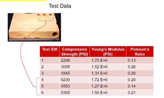
-
The sample should be prepared per the following:
- A homogeneous sandstone samples appx. 12” W x 24” L x 24” H (30 x 60 x 60 cm) for the final demonstration
-
Please contact Drillbotics at competition@drillbotics.com if you have difficulty obtaining your sample.
Targets
The targets will not be available until immediately prior to the Phase II test. However, the starting directional plan to hit the targets will not require wellbore inclinations in excess of 30° from vertical, 15° change in azimuth. Note: This is a maximum. Be prepared for much smaller build rates.
Trajectory
Teams shall choose their own trajectory to optimize the drilling, the well path and closeness to the given targets. This should be computed autonomously after the targets are manually entered. Limit the scope to 2-D for both the steering model as well as the formation model.
for BHA/bit deflection behavior. Optionally, you may add 3-D steering if you need to make course corrections along the nominally 2-D well path.
Bits
-
Upon request, DSATS will send a bit to the finalist teams for use in Phase II. It is expected that the BHA and pipe will cause some difficulty, both for initiating drilling dysfunction and for sensor integration and data telemetry. The judges will look for creative concepts supported by sound reasoning showing an understanding of how the BHA, bit and drillstring function together, and how the downhole system measures, samples and transmits the drilling data.
-
Upon request, the bit shall be returned to the Committee following Phase II testing for reconditioning for use in future competitions.
-
One (1) PDC bit will be provided by DSATS to be used during the Phase II tests. For 2020-2021 the bit will be:
-
A micro-bit 1.5" in (38.1 mm) diameter and 2.0” in total length.
-
Low axial aggressiveness and high side aggressiveness (i.e. high bit anisotropy).
-
Bits will not be available before mid-April at the earliest.
-
-
Students are encouraged to consider bit wear prior to the final test and its impact on drilling performance during the onsite testing. Based on prior competitions, bit wear should be minimal, but some cutter damage is always possible. Teams will only receive at most one bit.
-
Student teams may build or buy similar drill bits to test their design with the rock samples they sourced. The students must not engage any third parties or receive professional assistance in designing their own bit, however manufacturing can be performed by a third party.
-
For the final competition, the students may use the directional drill bit provided by DSATS or use their own bit design. However, the dimensions of their bits must not exceed 1.5 inches in diameter and 2 inches long. This provision is made to enable students to fully optimize the bit design for their specific directional system.
Drillstring
-
Drillpipe
-
Preliminary typical tubing specifications for aluminum tubing are listed below to assist with the mechanical and electrical design of the rig. Stainless steel tubing or aluminum tubing is permitted for the competition but must use the same dimensions as below, or the nearest metric equivalent. Teams may choose durability over flexibility and shall explain their choice in the design report.
-
There is no restriction on drill pipe diameter or hole diameter.
-
DSATS will not be providing tubing to the competition teams.
-
The use of a metric equivalent of the tubing is permitted.
-
Tubing is usually available from various hobby shops such as K-S Hobby and Craft Metal Tubing and via Amazon and other suppliers.
-
-
Tool joints
-
Students may design their own tool joints as long as the design concept is included in the Phase I proposal.
-
Alternately, students may use commercially available connectors/fittings attached to the drillpipe using threads, epoxy cement or other material, and/or may use retaining screws if desired, as long as the design concept is included in the Phase I proposal.
-
A fitting used somewhat successfully in 2017 is available from Swagelock. In 2018, the winning team used a fitting from Vertex.
-
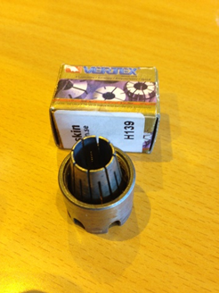 A fitting used successfully in 2016, but which did not work well in 2017, is available from Lenz (http://lenzinc.com/products/o-ring-seal-hydraulic-tube-fitting/hydraulic-straight-connectors) that uses a split-ring to allow a torque transfer across the fitting.
 -
Students must state WHY they choose a tooljoint design in the Phase I proposal.
-
-
Bit sub/drill collar/stabilizers
-
It is expected that each team will design and build their own bit sub. Instrumentation of the bit sub is ideal for directional sensors.
-
Additional weight may be added to the bit sub, or surface weight/force (above the rock sample) may be applied to provide weight on bit and drill pipe tension
-
Stabilizers are permitted but will be limited in length at the discretion of the Challenge Committee. Advise the committee of your choice and why and include this in the Phase I design for committee consideration.
-
Students must add sensors to the drillstring but are not permitted to instrument the rock samples. They must have a smaller diameter than the stabilizers and bit by at least 10%. Please include design concepts in the Phase I design.
-
The addition of along-string sensors to measure vibrations, verticality and/or tortuosity or other parameters will receive extra consideration. They must have a smaller diameter than the stabilizers and bit by at least 10%.
-
Automated Drilling
-
Drilling automation should be considered a combination of data, control AND dynamic modeling so that the control algorithm can determine how to respond to differences between the expected and actual performance. Process state detection can often enhance automation performance. Refer to documents posted on the DSATS website for more information.
-
Once drilling of the sample commences, the machine should operate autonomously. Remote operation and/or intervention is not allowed.
-
All directional control operations should be autonomously controlled by the drilling rig.
-
Manual intervention to add and/or remove a steering mechanism (e.g., whipstock) is permitted, however the determination/calculation of the orientation setting of the mechanism is required to be autonomous and must be shown on the rig floor display during each steering mechanism manipulation activity.
-
Length and timing of drilling modes (e.g., switching from slide drilling to rotational drilling, initiating the directional surveying procedure at the appropriate survey interval), must be autonomously determined/calculated and controlled.
-
Directional surveys acquired by the system need to be used as feedback for the steering control (and/or calculation of the steering requirements) logic.
-
-
Set-point commands for drilling parameters (WOB, RPM, ROP, etc.) should be optimized such that drilling dysfunctions are avoided, and drilling can be completed within the given time frame. Real-time optimization should be done automatically. The controllers need to ensure that the drilling parameters respond once the set points are altered.
Sensors
-
The team may elect to use existing oilfield sensors or may look to other industries for alternate sensors.
-
The team may develop its own sensors if so desired.
-
Sensor quality differs from data quality. Both are important considerations in this competition.
-
The final report shall address which sensors were selected and why. The sensor calibration process shall also be explained.
Data collection and handling
-
The team may elect to use standard data collection and recording techniques or may develop their own. Data handling techniques and why they were chosen should be described in the Phase I submittal.
-
The final report shall address which data systems were selected and why.
-
The observed response time of measurements, data aggregation and control algorithms should be compared to the Phase I estimates and published in the final report.
-
Describe how data is measured, aggregated, stored and retrieved. Describe calibration and data validation techniques used.
Data visualization
-
Novel ways of presenting the data and progress of drilling in real time while drilling will receive particular attention from the judges.
-
Visualization of the processes (automation, optimization, drilling state, etc.) should be intuitive and easily understood by the judges, who will view this from the perspective of the driller operating a rig equipped with automated controls.
-
Data must be presented in a format that allows the judges to easily determine bit depth, elapsed drilling time, ROP, MSE, verticality/inclination, vibration, and any other calculated or measured variable used to outline the drilling rigs performance to the judges. Lack of an appealing and usable Graphic User Interface (GUI) will be noted to the detriment of the team.
-
All depths shall use the industry-standard datum of rotary/kelly bushing interface (RKB), which should be the top of the rig’s “drill floor.”
-
An End of Well (EOW) report should be provided to the judges at the conclusion of drilling.
Measure and analyze the performance
-
The drilling machine should react to changing “downhole” conditions to select the optimal drilling parameters for improved performance, as measured by the rate of penetration (ROP), mechanical specific energy (MSE), verticality, cost per foot or meter, and other standard drilling measures or key performance indicators. Adding parameters such as MSE, or similar features, to the control algorithms will receive special attention from the judges.
-
Design limits of the drilling machine shall be determined and shall be incorporated in the programming of the controls during the construction phase.
-
Downhole measurements from directional sensors are to be used for adjusting drilling parameters and control of drilling machines used to aid in directional drilling.
Not included in the 2021-2022 competition
-
The drilling will not include automating the making or breaking of connections. If connections are necessary due to the rig and drillstring design, connections should be made manually, and the time involved with the connections will be included with respect to its effect on drilling performance (rate of penetration reduction).
-
A rig move, walking or skidding is not required, but the mobility of the rig will be considered in the design phase.
Phase I Design Report
-
Teams will submit a detailed report containing detailed literature review, model assumptions, overall plan of the virtual system, including the system architecture, different layers (such as data layer, control layer etc.), mathematical framework for modeling and control schemes, a plan for implementation, and relevant details. It is preferable to include special section for the API, if other system need to interact with your system. Preliminary results from the virtual drilling rig model should be included, along with a discussion on the results.
-
There are numerous examples of previous reports on the Drillbotics website. Feel free to use this as a resource. Should a team choose to use the concepts in previous reports in their design, be sure to cite the source of the information to avoid plagiarism concerns.
-
A safety case shall be part of the Phase I design (see Appendix “B”). Include a review of potential hazards during the planned construction and operation of the rig, and for the unloading and handling of any rock samples or other heavy items. An example of a safety case will be posted on the Drillbotics.com website.
-
The Phase I design report should include a discussion regarding the major design features proposed (mechanical and otherwise) - are they scalable to today’s working rigs? If not, what would be needed to allow implementation?
-
The Phase I design report should include a discussion regarding the control scheme and algorithm - How is each individual measurement used in the control code? Are they all given equal weight, and if not, what criteria is used to assign importance? What is the expected response time of the control system’s key components? How will this affect equipment selection? The teams are encouraged to perform control simulations to verify the control scheme.
Phase II – Drilling Competition
- Phase II Activities
-
Monthly progress reports are due at the end of each month.
-
Teams will deliver a pre-recorded presentation for the Phase II test two weeks prior to the test:
-
The students will present a BRIEF summary of their final design, highlighting changes from their Phase I design, if any. Include an explanation of why any changes were necessary, as this indicates to the judges how much students learned during the design and construction process. Explain what key features have been deployed. Describe novel developments or things learned that were worthwhile. Also include how actual expenses compared with the initial estimate. At some time during your talk, let us know who the team members are and what background they have that pertains to the project. Try to include all your team members as presenters, not just one spokesperson. The committee wants to see if all team members have a good understanding of key issues.
-
Previous teams used a short PowerPoint presentation of about ten slides or so. Use any format you like.
- Phase II Testing
-
In the spring term of 2023, qualifying teams will build the rig and use it to drill rock. Drilling a deviated well to hit the required targets (see Appendix “A”), efficiently through the sample while controlling drilling dysfunctions is the primary technical objective of the competition. Scoring of the directional drilling component will be primarily based on the horizontal distance from the target coordinate at which each target vertical depth was intersected. The use of both surface and downhole measurements to control the drilling process in real-time is mandatory, failure to do so will result in a failing grade. To avoid disqualification due to a downhole sensor failure, redundant or immediately replaceable items should be part of the design and implementation. Time to replace a sensor will be added to the drilling time for calculation of ROP.
-
Prior to the start of the test:
-
Teams are to use manual control to pre-drill a vertical pilot hole not more than 1” deep measured from the rock’s top face. This hole is to be drilled using the competition drilling rig. Location of this pilot hole will be marked on each sample by the committee at the intersection of two lines drawn from opposite corners of the rock sample. Drillbotics could modify the starting point a few weeks before the contest, so design your rig and rock handline equipment accordingly.
-
At their option, teams may use a straight housing for the pilot hole and then replace it with the bent housing for the drilling. Also, it is permitted to use a bit with larger size for the pilot hole.
-
Teams may use glue or use a mechanical fastener to attach a bell nipple or diverter housing to the top of the rock to allow connection of a flowline for return mud flow. The maximum allowable length of the bell nipple is 8 inches. If you use a fastener, be careful not to break the rock.
-
-
The drilling plan will be presented to the teams on the day of competition.
-
Presentations
-
The contest will begin with streaming of a pre-recorded presentation by each team. This will be followed by period of questions and answers (Q&A) via on-line or in-person or a hybrid of both. Teams will draw lots to determine the order of presentation. All teams may sit in for the presentations and Q&A of the other teams.
-
Depending on the time available, the actual test will start shortly after the last presentation of the day. It is possible that the presentations and tests could take two days to complete.
-
The presentations should include the details of the rig and downhole equipment and control schemes. If the team wishes to protect confidential proprietary concepts, please contact the Committee in advance so we can prepare accordingly to shield your ideas.
-
-
The Test
-
When the competition drilling begins, teams will be required to continue to drill the pilot hole vertically to the kickoff point. The kick off point may be at any depth greater than 4” below the surface of the rock. An RSS or AKO motor BHA will be specified on the day of the competition. Thus, the model should be capable of simulating both steering systems.
-
All rigs start the drilling competition at the same time.
-
Navigation shall be done autonomously
-
Manual intervention to add and/or remove a steering mechanism (e.g., whipstock) is permitted, however the determination/calculation of the orientation setting of the mechanism is required to be autonomous and must be shown on the rig floor display during each steering mechanism manipulation activity. The time to change orientation will affect the team’s ROP calculation.
-
No lateral forces are allowed to be applied above the top face of the rock.
-
No forces are allowed to be applied external to the rock that will force the drill bit in a particular direction
-
External magnetic field effects from the drilling rigs will be present on the directional sensors used to drill the wellbore. The industry has accepted practice of magnetic ranging. This may be a technique worth investigating to improve the signal to noise of magnetic measurements
-
Once drilling commences, the test will continue until the drill bit exits the rock sample, or three (3) hours, whichever comes first
-
-
Evaluation
-
Drilling performance will be observed and measured by Drillbotics judges invited to attend and witness the test. This could be a virtual event depending on travel restrictions. The details will be announced in early April 2023.
-
DSATS will judge the competitors primarily on their ability to hit the required targets as accurately (i.e. as close to target center at the given target vertical depth) as possible.
-
With respect to well path tortuosity, judges may insert a “flexible casing” to drift the wellbore to obtain a relative measure of borehole quality.
-
Scoring of the directional drilling component will be primarily based on the following criteria, with the weighting of individual items as indicated:
| Criteria | Parameter | Weighting |
|---|---|---|
| Phase I: | ||
| a. Safety | Safety: construction and operation | 10 |
| b. Mobility of rig | Rig up, move, rig down | 5 |
| c. Design considerations and lessons learned | 10 | |
| d. Mechanical design and functionality, versatility | 25 | |
| e. Simulation/Model/Algorithm | 25 | |
| f. Control scheme | Data, controls, response times | 25 |
| Total | 100% | |
| Phase II: | ||
| a. Creative Ability | Analysis, concepts, development | 10 |
| B .Engineering Skills | Problem/Goal, design criteria, feasibility | 10 |
| c. Construction Quality | 10 | |
| d. Cost Control | 10 | |
| e. Performance | 30 | |
| Various parameters such as: | ROP, MSE, Landing Bit, Inclination, and other | |
| Are these used within the control algorithms | ||
| Accuracy of drilled wellbore trajectory (see Appendix “A” for details) | Proximity of drilled wellbore to required target X/Y coordinates and vertical depths | |
| f. Quality of wellbore | Tested using the Go-No-Go flexible ‘Casing’ | 10 |
| Verticality, tortuosity, caliper, other | ||
| g. Data | Data handling, data visualization, data comparison to judges’ wellbore logs, and other |
|
| h. Downhole Sensor Data Used in Control Algorithm | Pass/Fail | Pass/Fail |
| Total | 100% | |
| Intangibles | Additional score may be added or subtracted by the judges at their discretion |
Final Report and Paper
The finalists shall prepare a project report that addresses the items below. We suggest you use the format of most SPE papers. For reference, please see http://spe.org/authors/resources/
-
The final report is simply an update following the Phase II test to explain what worked and what did not and to discuss future plans that would improve your design. The final report should outline drilling performance and efficiency criteria and measured results.
-
The winning team in Group B will need to start work on a abstract for their paper shortly after the Phase II test results are announced.
-
If the abstract is accepted, in August or September, the team needs to start writing their SPE paper. The abstract must generate sufficient interest with the SPE review committees to warrant publication, although DSATS will help promote acceptance elsewhere if necessary.
-
The timing for submittal of the abstract and paper will be the published deadlines per the call for papers and conference guidelines as posted on the SPE’s website (
). -
The paper should address at a minimum:
-
The technical and economic considerations for the control system, rig, and BHA design, including why certain features were chosen and why others were rejected.
-
The setup of the experimental test, the results and shortcomings.
-
Recommendations for improvements to the design and testing procedures.
-
Recommendations for improvements by DSATS of the competition guidelines, scheduling and provided material.
-
Areas of learning gained through the competition not covered in the university course material.
-
A brief bio or CV of the team members and their sponsoring faculty.
-
Note that the SPE audience already knows a lot of the background information that you presented the judges to demonstrate your capabilities, so adjust the paper content accordingly.
-
Appendix B: Automation & Interface Design from a Human Factors Perspective
Background on Automation
Any complex, engineered system that is wholly reliant upon human operators to achieve its goal is likely to experience issues. Humans are inconsistent when performing monitoring tasks, they tend to not make wholly rational decisions, are impacted by external factors and are prone to error. As technology advances and complexity increases (such as the control regimes proposed in remote drilling operations for example) such issues become more prevalent. However, many of the issues associated with such complexity can be countered by reallocating certain tasks to automation.
The concept that 'machines' (read automation) are better at some tasks than humans and vice versa has been prevalent for decades. The original incarnation of this notion was presented in 'Fitts List' [Ref. 1]. 'Fitts List' is 11 statements designed to provide guidance on 'what humans are best at' compared to 'what machines are best at' for example:
Humans surpass machines in respect to:
- 'Their ability to improvise and use flexible procedures'
Machines surpass humans in respect to:
- 'Their ability to handle highly complex operations i.e., to do many different things at once'.
Although Fitts List was originally published in 1951, the vast majority of the statements still ring true today (after all humans have changed very little in the last 70 years) but with advances in research and technology, automation is now viewed on a sliding scale (from wholly manual to wholly autonomous) This has recently been subject to consideration by the Drilling Systems Automation Roadmap who have chosen to adopt a 10-point level of automation taxonomy as follows [Ref. 2]:
1. The computer offers no assistance, and the human must do it all
2. The computer suggests alternative ways to do the task and the human selects from those suggestions and executes the task
3. The computer selects one way to do the task, which triggers five possible scenarios including:
-
the human executes that selection
-
the computer executes that suggestion if the human approves
-
the computer allows the human a restricted time to veto before automatic execution
-
the computer executes the suggestion automatically necessarily informs the human
-
the computer executes the suggestion automatically and informs the human only if asked
4. The computer selects the method, executes the task, and ignores the human.
Superficially, for highly complex systems, it may appear that there are very few downsides to providing very high levels of automation with little to no required user input. However, as is often stated, there is no such thing as a 'free lunch' and there are often overlooked downsides to providing high levels of automation usually termed the ‘Ironies of Automation’ [Ref. 3] which must be suitably managed. Two examples of this are:
1. Any autonomous system is ultimately conceived and designed by humans – Attempts to design out the human merely shift the responsibility further up the chain. Operators involuntarily inherit the biases and Performance Shaping Factors that influenced the design team.
2. The autonomous system cannot account for unforeseeable scenarios – This is one of the predominant reasons humans remain part of complex systems, to address the ‘unknown unknowns’. However, expecting human operators to flip between a passive ‘monitoring’ role and an active ‘doing’ role is difficult to achieve, they may be ‘out of the loop’ and their Situation Awareness may be compromised.
Maintaining appropriate levels of automation and ensuring that your ‘projected’ drilling operator remains ‘in the loop’ through good interface design will be one of the key challenges you will face in the Drillbotics competition.
Resources
The following resources have been selected to assist you in the design of your drilling interface and the levels of autonomy you decide upon. Where possible free resources have been chosen (either available through OnePetro or elsewhere on the Internet) but two textbooks have also been selected as they offer an excellent primer on usability heuristics and the importance of good design.
1. de Winter JCF, Hancock PA. Reflections on the 1951 Fitts List: Do Humans Believe Now that Machines Surpass them? Procedia Manufacturing. 2015;3:5334–41.
Useful for reference, refer to Table 1 in particular for the original Fitts list.
2. Parasuraman R, Sheridan TB, Wickens CD. A model for types and levels of human interaction with automation. IEEE Trans Syst, Man, Cybern A. 2000 May;30(3):286–97.
Automation taxonomy chosen by the DSA.
3. HUMANFACTORS101. The Ironies of Automation [Internet]. Human Factors 101. 2020 [cited 2021 Sep 9]. Available from: https://humanfactors101.com/2020/05/24/the-ironies-of-automation/
A condensed version of the so called 'ironies of automation' as originally written by Lisanne Bainbridge.
4. Norman DA. The design of everyday things. Revised and expanded edition. New York, New York: Basic Books; 2013. 347 p.
A seminal text, a little dated in terms of examples but provides great insight into the impact of poor design.
5. Lidwell W, Holden K, Butler J. Universal principles of design: 125 ways to enhance usability, influence perception, increase appeal, make better design decisions, and teach through design ; [25 additional design principles ]. rev. and updated. Beverly, Mass: Rockport Publ; 2010. 272 p.
An excellent 'style guide' to assist in designing your drilling interface.
6. Lauche K, Sawaryn SJ, Thorogood JL. Human-Factors Implications of Remote Drilling Operations: A Case Study From the North Sea. SPE Drilling & Completion. 2009 Mar 15;24(01):7–14.
Consideration of the implications of remote drilling operations from an impact on current work practices perspective.
7. Experience WL in R-BU. 10 Usability Heuristics for User Interface Design [Internet]. Nielsen Norman Group. [cited 2021 Sep 9]. Available from: https://www.nngroup.com/articles/ten-usability-heuristics/
A condensed take on a number of key usability heuristics.
8. Human factors/ergonomics – Alarm management [Internet]. [cited 2021 Sep 29]. Available from: https://www.hse.gov.uk/humanfactors/topics/alarm-management.htm
HSE background information on alarm management and prioritisation.
9. EEMUA Publication 191 Alarm systems - a guide to design, management and procurement. Available from: https://www.eemua.org/Products/Publications/Digital/EEMUA-Publication-191.aspx
This is a lengthy publication dedicated to alarm system design, will be useful for additional, wider reading. EEMUA membership is required otherwise the document requires payment.
10. Henderson J, Wright K, Brazier A, Great Britain, Health and Safety Executive. Human factors aspects of remote operation in process plants. Great Britain, Health and Safety Executive; 2002.
Useful background for wider reading.
11. Johnsen SO, Holen S, Aalberg AL, Bjørkevoll KS, Evjemo TE, Johansen G, et al. Automation and autonomous systems: Human-centred design in drilling and well. :150.
Report commissioned by the Petroleum Safety Authority Norway. Very comprehensive with some good case study examples included.
Appendix C: Additional References
-
Florence, F., Losoya, E., Drillbotics with Fred Florence and Enrique Losoya (2020, August 18), SPE Podcast, Link.
-
Pessier, R. C., & Fear, M. J. (1992, January 1). Quantifying Common Drilling Problems With Mechanical Specific Energy and a Bit-Specific Coefficient of Sliding Friction. Society of Petroleum Engineers. doi:10.2118/24584-MS
-
Menand, S., Simon, C., Gerbaud, L., Ben Hamida, M., Denoix, H. J., Cuillier, B., Sinardet, H. (2012, January 1). PDC Bit Steerability Modeling and Testing for Push-the-bit and Point-the-bit RSS. Society of Petroleum Engineers. doi:10.2118/151283-MS
-
Pehlivantürk, C., D’Angelo, J., Cao, D., Chen, D., Ashok, P., & Van Oort, E. (2019, March 4). Slide Drilling Guidance System for Directional Drilling Path Optimization. Society of Petroleum Engineers. doi:10.2118/194096-MS
-
Marck, J., Detournay, E., Perturbation to Borehole Trajectory across an Interface, ARMA-2014-7479, 48th US Rock Mechanics/Geomechanics Symposium, Minneapolis, Minnesota, June 1-4, 2014.
-
Zalluhoglu, U., Marck, J., Gharib, H., & Zhao Y. (2019) Borehole Propagation with Undergaged Stabilizers: Theory and Validation. ASME Journal of Dynamic Systems, Measurement and Control, vol. 141, no. 5: 051013. doi: 10.1115/1.4042380
-
Perneder, L., Marck, J. and Detournay, E., 2017. A model of planar borehole propagation. SIAM Journal on Applied Mathematics, 77(4), pp.1089-1114. doi: 10.1137/16M1094518
-
Zalluhoglu, U., Demirer, N., Marck, J., Gharib, H., & Darbe, R. (2019) Steering advisory system for rotary steerable systems. SPE/IADC Drilling Conference and Exhibition, 5-7 March, The Hague, The Netherlands. SPE-194090-MS, doi: 10.2118/194090-MS
-
Zalluhoglu, U., Gharib, H., Marck, J., Demirer, N., & Darbe, R. (2019) Steering advisory system for mud motors. SPE/IADC Drilling Conference and Exhibition, 5-7 March, The Hague, The Netherlands. SPE-194077-MS. doi: 10.2118/194077-MS
-
Franklin, G. F., Powell, J. D., Emami-Naeini, A., & Powell, J. D. (1994). Feedback control of dynamic systems, 3rd Edition, Reading, MA: Addison-Wesley.
-
Ogata, K. (2003). System dynamics, 4th Edition, Upper Saddle River, NJ: Prentice Hall.
-
Ogata, K. (2009). Modern control engineering, 5th Edition, Upper Saddle River, NJ: Prentice Hall.
-
Li, Y., Ang, K. H., & Chong, G. C. (2006). PID control system analysis and design. IEEE Control Systems Magazine, 26(1), 32-41.
-
Rawlings, J. B. (2000). Tutorial overview of model predictive control. IEEE control systems magazine, 20(3), 38-52.
-
Webinar: Machine Learning and Physics-based Solutions for Drilling Automation by SPE Distinguished Lecturer Prof. John Hedengren, Brigham Young University, YouTube Video.
-
Webinar: Drilling Automation and Downhole Monitoring with Physics-based Models. Link.
-
Video and Webinar Series: Understanding Control Systems by Mathworks. Link.
Archive: 2024
This page preserves the original 2024 guidelines content as-is for historical reference. For the current rules, see the pages under "Competition" and "Tracks".
-
Publication is subject to the SPE program committee’s acceptance of the abstract/paper. If the abstract is not accepted, DSATS will solicit other SPE events to try to get the paper into OnePetro. Travel authorization will depend on any international or local travel restrictions in place at the time of certain events. ↩
-
DSATS will submit an abstract to SPE, and if need be, to other organizations, in an effort to help teams publish the results of their work. The acceptance of any abstract depends solely on the program committees of such venues. ↩
-
Subject to continued approval by the conference program committee. ↩
-
Subject to continued approval by the SPE conference staff. ↩
-
Travel authorization will depend on any international or local travel restrictions in place at the time of certain events. ↩
-
A housing unit could be a shared property from such sources as Expedia, Air B&B or similar entities. ↩